The structural analysis software RFEM 6 is the basis of a modular software system. The main program RFEM 6 is used to define structures, materials, and loads of planar and spatial structural systems consisting of plates, walls, shells, and members. The program also allows you to create combined structures as well as to model solid and contact elements.
RSTAB 9 is a powerful analysis and design software for 3D beam, frame, or truss structure calculations, reflecting the current state of the art and helping structural engineers meet requirements in modern civil engineering.
Do you often spend too long calculating cross-sections? Dlubal Software and the RSECTION stand-alone program facilitate your work by determining section properties of various cross-sections and performing a subsequent stress analysis.
Do you always know where the wind is blowing from? From the direction of innovation, of course! With RWIND 2, you have a program at your side that uses a digital wind tunnel for the numerical simulation of wind flows. The program simulates these flows around any building geometry and determines the wind loads on the surfaces.
Are you looking for an overview of snow load zones, wind zones, and seismic zones? Then you are in the right place. Use the Geo-Zone Tool to determine quickly and efficiently snow loads, wind speeds, and seismic data according to ASCE 7‑16 and other international standards.
Would you like to try out the capabilities of the Dlubal Software programs? You have the opportunity to do so! The free 90-day full version allows you to thoroughly test all our programs.
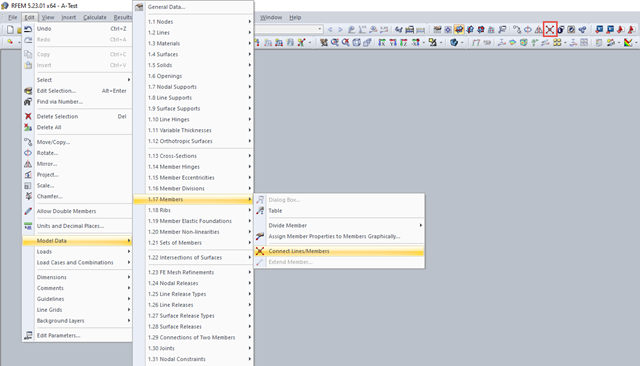
The function you are looking for is "Connect Lines/Members". You can use this by selecting the menu item Edit → Model Data → Members → "Connect Lines/Members" or using the corresponding toolbar button (see Image 01).
After activating the command, a window is opened via the connection point. A node is created between the intersecting members.
There is an option to convert an intersection to a line. This option allows you to create the intersection manually. Here is an example:
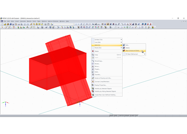
1. First, an intersection between two objects is created, here using the "New Compound Solid" command:
In this specific case, the cylinder is subtracted from the cuboid, thus creating an intersection:
2. This intersection is now "converted into lines". For this, select all involved objects and in the shortcut menu, select "Convert into Line" under "Intersection":
3. The new lines are used to create new surfaces or modify existing ones. You can change the boundary lines of a surface by selecting them again. In particular, the intersection area must be modeled as a quadrangle surface:
4. Finally, it is necessary to create the solid again:
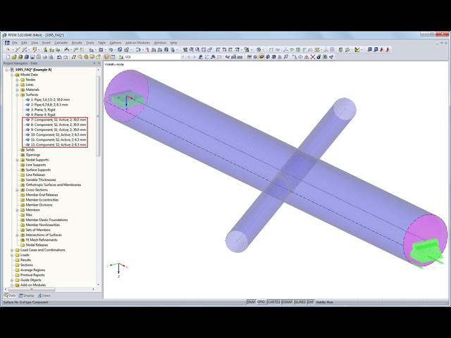
By creating an intersection, additional components are created in addition to the actual surfaces that represent, for example, the intersecting pipes. After generating the intersection, all components are initially active. This can be seen in the Data navigator under the entry for surfaces.
You can deactivate the individual components subsequently. To do this, you can either click the entry in the navigator or select the respective component in the model. In the dialog box for editing the component, this can be deactivated.
You can also use the corresponding shortcut menu (right-click on the component) in the Data navigator to deactivate the component.
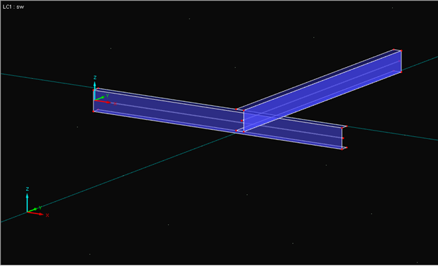
Depending on the requirements, there are various options. As an example, two intersecting channel sections serve as surface models, as shown in Image 01. The spacing of the sections is comprised of one-half the surface thickness in each case, since center surfaces are modeled in RFEM.
For Option 1, a bolt is modeled between both surfaces. It is important to ensure that the load introduction of a single node into a surface creates a singularity (Image 02). Below, you will find a link to an article showing how to prevent this kind of point load introduction and a link to an article showing how to model a hole bearing. In the case of this simpler option, the bolt must also absorb compressive forces, as the surfaces do not rest on each other.
Option 2 additionally uses a contact solid (see the description by clicking the link). In the contact solid, you can set how the forces should be transferred. If the contact solid is in tension, the bolt will be in tension and the surfaces in compression (Image 03).